As originally designed, the transceiver supplies the modest power requirements of the IsoCat internal audio buffer. In some instances, it may be more convenient to obtain buffer power from the isolated USB power source. This the case with the current Yaesu transceivers, as well as some older transceivers. Obtaining the power from the IsoCat may also make cabling more convenient when transceiver auxiliary power is not available on the same connector that provides the audio output and modulator input.
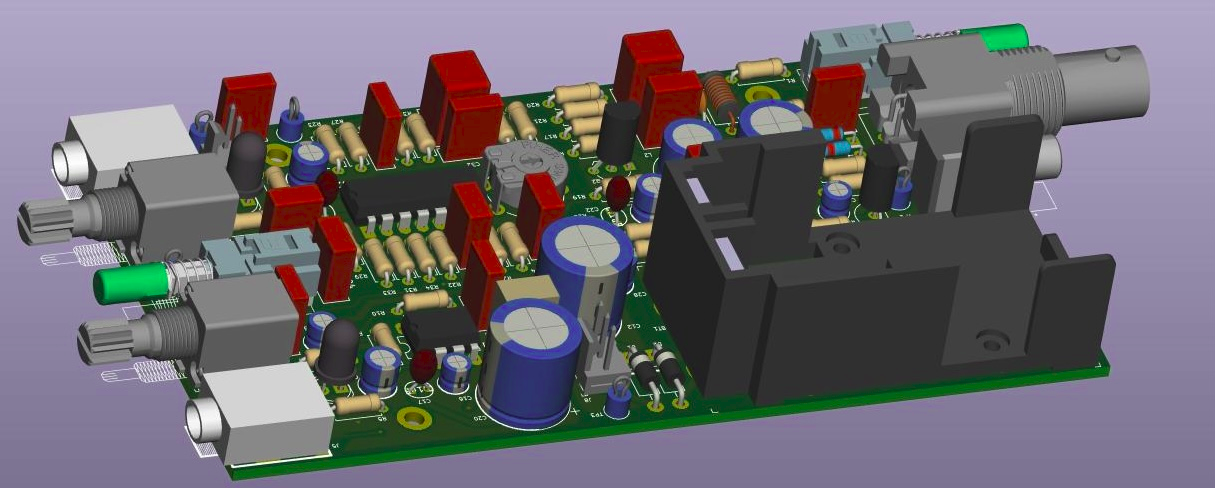
PC board modification
Obtaining buffer power from the isolated +5V supply is relatively simple, either during card assembly or after the interface is completed. Two jumpers bring +5V and ground from the isolated USB supply to the sound card buffer. See the revised schematic and the photo for details.

IMPORTANT: To avoid possible damage to the interface or the transceiver, be sure to cut the +8V trace from the transceiver interface connector.
To avoid possible damage to the IsoCat CI-V circuitry, verify that the voltage from the grounded end of R20 to the junction of R21 and R22 is between 4.75 and 5.5 volts. If it is greater than 5.5 volts, add a 220 to 100 ohm, 1/8 W resistor to load the +5 supply.
Alternate cabling
Depending on transceiver make and model, cabling may be greatly simplified as a result of this modification. For example, the cabling for the FT-817, FT-857, and FT-897, the power cable between the CAT connector and the data connector is not necessary after this modification. This makes for a much neater cable set. See the cabling diagrams for the cabling details.
Yaesu 897 menu settings
Suggested settings are green.
MENU MODE No•037 [DIG GAIN]
- Function: Adjusts the audio input level from terminal equipment (such as a TNC or PSK-31sound card) during DIG (Digital) mode operation.
- Available Values: 0 ~ 100
- Default: 50
MENU MODE No•038 [DIG MODE]
- Function: Selects the mode and sideband (if applicable) in the DIG (Digital) mode.
- Available Values: RTTY-L/RTTY-U/PSK31-L/PSK31-U/USER-L/USER-U
- Default: RTTY-L
- RTTY-L: AFSK RTTY operation on the LSB mode
- RTTY-U: AFSK RTTY operation on the USB mode
- PSK31-L: PSK-31 operation on the LSB mode
- PSK31-U:PSK-31 operation on the USB mode
- USER-L: User-programmed custom operation based on LSB mode
- USER-U: User-programmed custom operation based on USB mode
In the USER-L and USER-U modes, you can define the display frequency offset and carrier frequency offset by Menu Mode No-036 [DIG DISP] and No-039 [DIG SHIFT].
Either option should work. This seems to be more about changing the display than changing the internal switching.
MENU MODE No•039 [DIG SHIFT]
- Function: Defines the carrier frequency offset during DIG (USER-L or USER-U) mode operation.
- Available Values: –3000 ~ +3000 Hz
- Default: 0 Hz
MENU MODE No•071 [PKT1200]
- Function: Adjusts the audio input level from the TNC during 1200 bps Packet operation.
- Available Values: 0 ~ 100
- Default: 50
MENU MODE No•072 [PKT9600]
- Function: Adjusts the audio input level from the TNC during 9600 bps Packet operation.
- Available Values: 0 ~ 100
- Default: 50 Set to 0
MENU MODE No•073 [PKT RATE]
- Function: Sets the transceiver’s circuitry for the Packet baud rate to be used.
- Available Values: 1200/9600 (bps)
- Default: 1200 (bps)
Before attempting to transmit, select an appropriate digital mode frequency and USB mode, turn the transmit power down to 20 or 25 watts, and switch the radio to digital mode. Turn the computer output sound level all the way down, and then initiate a short test transmission. Slowly bring the sound level up to see if you get output. Monitor the ALC level and set the sound level to just below the point where you see ALC activity.